Content contributed by:
If you own a press brake that is eight feet or longer, chances are you’ve experienced press brake deflection. Press brake deflection is when the ram and bed flex under load. Most modern press brakes are powered by two hydraulic cylinders on either end and are supported by side frames, meaning that both the power and support are isolated to either end of the machine. This results in the machine being the strongest and most rigid at the two ends. As a result of this design, ram and bed deflection is a normal part of press brake operation. Ram and bed deflection occurs most dramatically in locations farthest away from the hydraulic cylinders; in other words, it is most noticeable in the middle of the press brake.
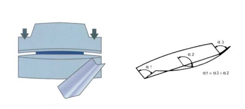
as a result the angle produced will be more obtuse in the center of the work piece
While press brake deflection is a natural occurrence in modern press brake operations, it can pose challenges to getting consistent bend angles, particularly across the entire length of long parts. Because the ram and bed deflect in the shape of an arc, the angle produced will be more obtuse in the center of the work piece, or at the peak of the arc. For instance, imagine you are bending a 90° angle across the length of a 10 foot part. While the ends of the finished part may be an accurate 90°, you could end up with as much as a 98° bend angle in the center. This phenomenon is known as the “canoe effect.”
There are a variety of methods used to compensate for press brake deflection, some of which are more effective than others.
Shimming
Shimming is the most basic method of compensating for press brake deflection and is achieved at the operator level. perators incrementally insert thin pieces of metal, paper, or cardboard underneath the dies. This process adds height to the dies in areas where your bend angle is greatest, closing up the produced angle. Shimming is an extremely time consuming and inconsistent process. It should be avoided at all costs, serving only as a last resort when all other methods have been exhausted. Shimming is an art form that requires a skilled and experienced operator. However, even when performed by the most skilled operators, it typically requires multiple test bends, which result in excess scrap material and can eat up valuable production time. It is also worth noting that shimming can lead to premature wear on tooling and other components. Find out how much shimming is costing you.
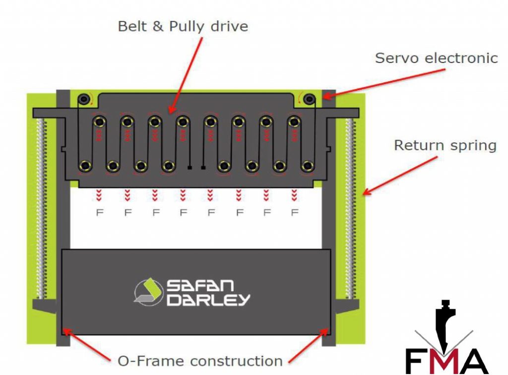
Servo-Electronic Pulley Press Brakes
Some modern press brakes utilize a servo-electronic pulley system that can often eliminate press brake ram and bed deflection. Because the design distributes force more evenly across the full working length of the machine, deflection is virtually nonexistent when used properly. What does “proper use” entail? Most machines require the use of dies with V-openings that are equal to eight times the material thickness. When using V-openings of less than eight times the material thickness, deflection may still occur. Check with the manufacturer for the recommended use for maximum accuracy.
Hydraulic Crowning
Some press brakes come from the factory with hydraulic crowning already built in. Hydraulic crowning uses hydraulic cylinders located in the bed of the machine. As the cylinders are filled with hydraulic pressure, they exert an upward force on the bed of the machine to compensate for deflection. Modern hydraulic crowning systems often feature what is known as dynamic crowning. Dynamic crowning provides a unique benefit of monitoring inconsistencies and resistance during the bending process, allowing for it to make real time adjustments to correct not only inconsistencies in the press brake but inconsistencies in the material as well.
Mechanical Crowning
By far the most common solution to compensating for deflection is mechanical crowning systems. Mechanical crowning systems are installed in place of a bottom tool holder, as they also serve this function. They typically feature either mechanical or hydraulic clamping as options. They also typically feature different drive designs, from analog to digital readouts and from hand crank assemblies to CNC motors. Mechanical crowning systems can typically be outfitted to the press brake at the time of purchase, as well as after the purchase in the form of a retrofit. Mechanical crowning systems vary in design, accuracy, and ease of use from product to product. Unless your press brake has a hydraulic crowning system, a mechanical crowning system will probably be the solution you need to compensate for deflection. Don’t make the mistake of assuming all mechanical crowning systems are made equal and buying just any system.
Consider your applications, your challenges, and determine the set of features you need to increase your productivity and efficiency before making the investment. Questions or need to brainstorm? Your FMA Sales Engineer is here to HELP.